Homemade Panohead
(see also improvements ...)
Seamless panoramic pictures of the immersive 360° virtual reality type require a way of rotating the camera about the point of zero parallax within the lens, often called its nodal point (or entrance pupil, etc.). For panoramas that include lots of foreground this is critical, and is achieved with a panoramic tripod head (panohead), which allows smooth pan and reproducible tilt motions.
There are several commercial panoheads but they are either too expensive or look cheap and flimsy. There are also a few do-it-yourself panoheads described on the web. Although some of these may work well enough, most are pretty amateurish and the wooden ones seem way too bulky. Most homebuilt heads rely on the tripod for rotation or have rudimentary rotation mechanisms. The better homemade panoheads tend to employ expensive commercial bits and pieces for these tricky parts (e.g. from Novoflex or Manfrotto etc.).
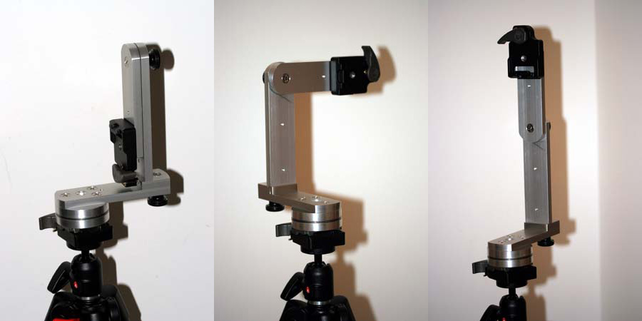
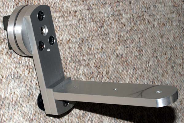
I decided to build my own from scratch. It had to be sturdy, well made, precise, and small. It also had to be capable of multiple rows at any pitch, and cast a footprint much smaller than the tripod legs. The ability to adjust for different camera/lens combinations is not important to me, but must be trivial if the need arises, i.e. no more work than a simple drillhole. For me it must work exactly the same way every time, with as little fuss as possible. A similar philosophy seems to have governed the design of the original but now defunct (?) 360Precision head, but it cost a fortune, weighed a ton, and appeared to cast a large footprint. Once I had a reasonable understanding of my requirements, I made this:
The three arms and the footplate of the vertical section were hacksawed from a piece of clear-anodized aluminium bar that was 10 x 40mm in cross-section by ~600mm long, and the two disks for the rotating base are from a piece of scrap 3/8" plate. If buying material to make another I'd probably use something like 5/16". The only power tool used in making this device was a Delta drill press. It would have been harder, but not impossible, to make it without it.
The panohead is easy to disassemble - the exploded view below shows all the parts:
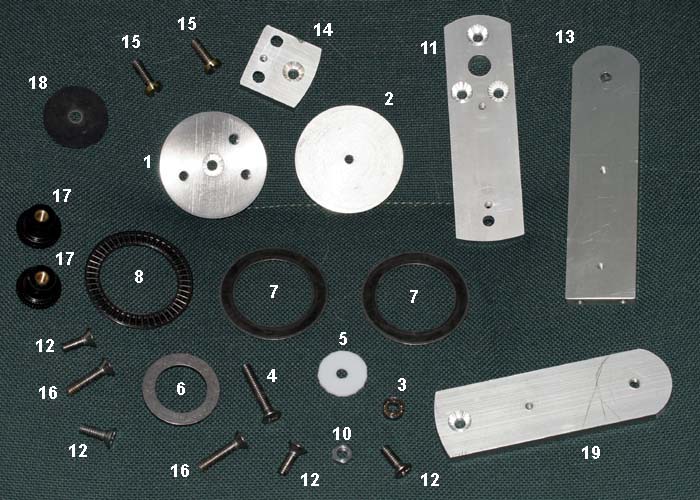
The first step was to make the two disks (1 and 2). These were hacksawed, roughly cut, and coarse filed to a diameter of slightly over 2.5". They were stacked together, drilled (3/16" I think - the bit came with a 1/4-20 thread tap), and threaded as one piece so that the threaded holes lined up exactly. The hole in disk 1 was later widened to 1/4" and countersunk, and three other holes in disk 1 are also threaded, but were drilled and tapped later (vide infra). All the nuts and bolts in the finished head have the same 1/4-20 thread.
Without a lathe, making the disks circular required some effort. Both rough-cut threaded disks 1 and 2 were screwed onto a single 1/4-20 bolt and fastened tightly in place with nuts similar to 10 in the picture. This assembly was mounted in the drill press and roughly filed with a coarse flat bastard file (that's what they are called, but I don't know why), i.e. drill press acting as a sort of vertical lathe, but it proved impossible to get the disks perfectly round. To get better circles, a sanding disk was attached to the drill press and a jig (wood and angle brackets) made to hold the disk assembly. With the drill running as slowly as possible and the disk/jig positioned just right and with manual turning of the disks in the jig it was possible to abrade away just the right amount to achieve near perfect circles. The scratch marks were cleaned up with successively finer-grade sanding disks. Final finishing was done with some scraps of 600-grit emery paper. After a few hours the two disks were identical and essentially perfect.
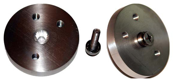
The hole in disk 1 was then widened to 1/4" and deeply countersunk, i.e., the countersink bit was forced down a couple of millimetres or so further than normal. This allows the small ball-bearing race 3 to fit snug (but not flush) inside it. This small bearing was another bit of junk that I had lying around. The bearing 3 fits on the 1.5" countersunk bolt 4 which then slots into the hole in disk 1 (remember, at this point there was only one hole in disk 1 - the pictures were taken after it was complete), viz.
This assembly was built into a smoothly rotating base using pieces 5 - 8 and disk 1, like this:
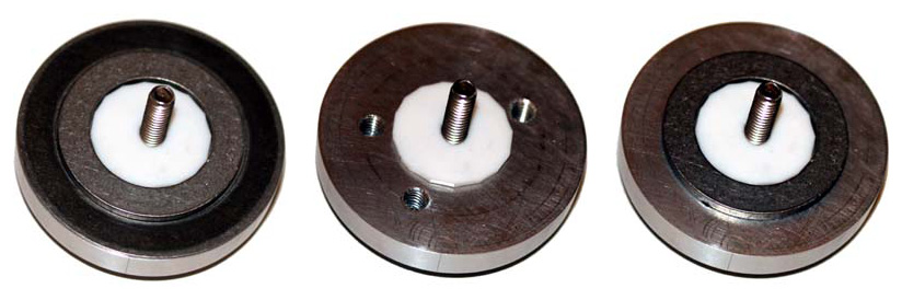
with teflon disk (5), thick steel washer (6), thin steel washer (7)
Piece 5 is a teflon disk, roughly cut with a razor blade. Piece 6 is a thick steel washer (McMaster-Carr). I had originally intended to make a detent ring out of this but now it just acts along with the teflon disk to prevent bearing slippage. I found an easier way to ensure precise rotation (vide infra). If I were to make another I'd probably discard piece 6 and just make piece 5 larger. Incidentally, piece 5 need not be made of teflon: any plastic, wood or even thick cardboard would probably suffice. I used teflon because I had originally intended to make a teflon bearing but it just didn't have the right feel. Of course, anyone with access to a lathe could hollow out a recess for the bearing and hence disregard pieces 5 and 6 altogether.
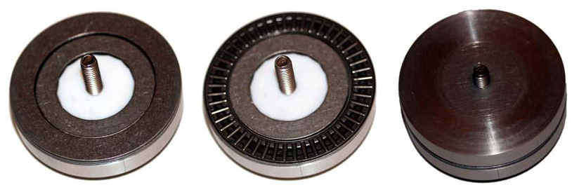
with thrust bearing (8), second steel washer (7), disk (2) in place
The roller bearing 8, which is 2.5" in diameter, and thin steel washers 7, were also from McMaster-Carr and cost just a few dollars. It is the size of this bearing and the tension with which the disks 1 and 2 are held on to it that define the degree of flex within the rotating base. By way of comparison, the base on the old 360Precision head had a similar sized bearing in spite of its much larger base. They claimed essentially no flex in their component, and I believe them because mine does not flex either! A Manfrotto quick-release plate is attached firmly in place with nut 10.
The rotation of this assembly is very smooth and precise. It should be made tight enough that it does not slip when the whole panohead plus camera is attached slightly cockeyed to a tripod, but still allows easy fingertip positioning. This is not difficult to achieve.
The next piece of the panohead is the horizontal beam 11. Since dimensions will vary for different camera/lens combinations, exact measurements are not given. Besides, half the fun of a project like this is to figure things out during the build. The large hole in piece 11 was drilled to 0.5" diameter and then widened slightly by careful filing to accomodate the ball bearing and bolt of the rotating base. The rotating base was disassembled and disk 1 was clamped tightly to piece 11 and the three other holes were drilled. The three new holes in disk 1 were tapped, while those in piece 11 were widened to 1/4" and countersunk.
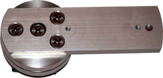
Piece 11 is firmly attached to the rotating base assembly by three of the short countersunk bolts 12. These bolts do not emerge on the other side of disk 1, if they did they would interfere with the washers 6, 7 and thrust bearing 8 and thereby mess up the rotation. The bolts I had were all too long so I cut them and filed the ends smooth. All these bolts may be overkill, but I like the symmetry. The smaller bolt holes visible in piece 11 (and also pieces 13, 14 and 19) were present to begin with and have nothing to do with my design. The curve at the end of piece 11 that attaches to the rotating base was carefully filed and smoothed to match the curvature of the disks, and the other end was also given a gentle curve, like this:
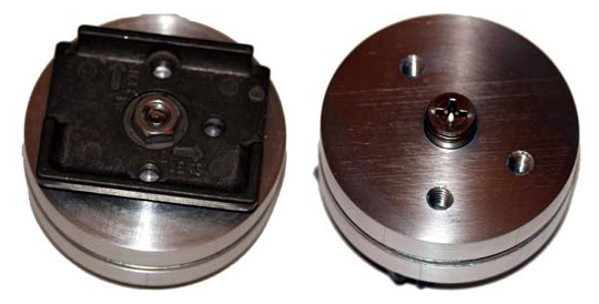
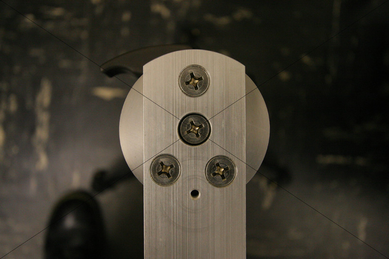
The main upright part of the panohead is in two pieces, a vertical riser 13 and a base 14, held together by two panhead bolts 15. I used panheads here rather than countersunk bolts to give a small amount of adjustability. This adjustment needs to be made correctly just once because these pieces need never be detached again. This joint is completely flex free.
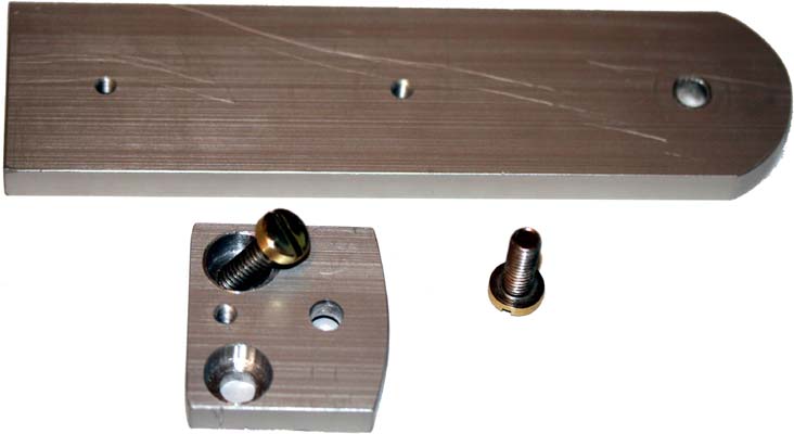
It is not possible to see in the picture immediately above (they are just visible in the exploded view, vide supra), but the riser 13 has two threaded holes into which the bolts 15 are fastened to hold the base 14 in place, like this:
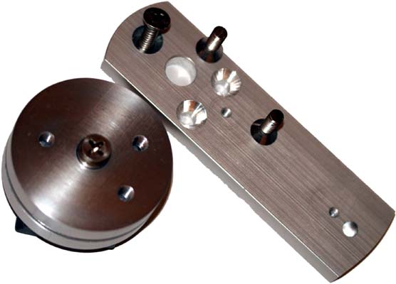
Surprisingly, this was the hardest part to get right because the pieces need to be aligned at as near to right angles as possible. Still, any halfway decent machinist (a claim that I do not make for myself) could get it essentially perfect with little effort. In any event, the vertical assembly attaches to the horizontal beam 11 via a countersunk hole in base 14 with one of the bolts 16 and a knob 17, i.e. these parts:
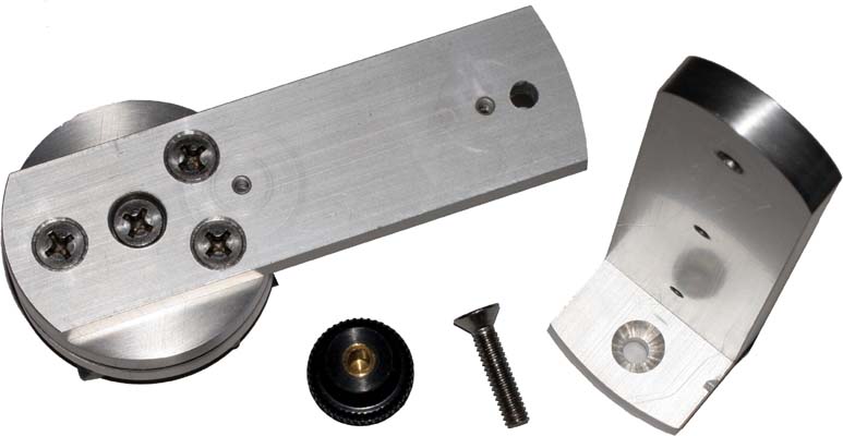
become this:
Again, this connection is devoid of flex, even under substantial load. The curved ends of beam 11 and base 14 were later filed and smoothed together so that their curves match. This makes it trivial to fix it all back together within acceptable tolerances just by feeling for misalignment with the fingertips while holding it firmly on a flat surface. The position of the vertical riser 13 on the horizontal beam 11 was set so that the middle of the cross on the Phillips head of bolt 4 was exactly centered in the camera lens with the camera mounted on the panohead pointing straight down. Perhaps by chance this was easy to achieve in practice but it would be possible to shim some of the connections if it had been a little off.
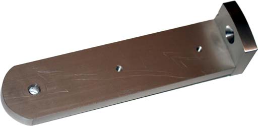
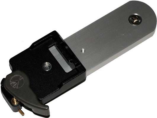
The last piece of the panohead is arm 19 that the camera attaches to. It is fitted at one end with a Manfrotto quick release base and the other end is filed and smoothed to match the curvature of the top of vertical riser 13.
Arm 19 is attached to riser 13 with the other bolt 16 and knob 17. These knobs were retrieved from a junk drawer and so cost me nothing. A circle of thin rubber sheet 18 placed between 13 and 19 prevents slippage. This connection does not have to be excessively tight because of the friction imparted by the rubber gasket. Given the appropriate tightness there is essentially no flex in this joint either, at least under the load of my camera/lens combination. Fully assembled, my panoramic head looks like this:
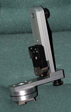
The rotating base and camera arm elbow are freely manoeuvrable over a full 360°. With a reduced-frame camera such as the Canon 20D or Nikon D70 and a lens like the Canon EF-S 10-22 or Sigma 10-20 @ 10mm, six shots each at +35°, -30° and a single zenith shot work well. At the moment these angles are simply drawn in pencil on piece 13, but a more permanent and reproducible solution is planned. It is even possible to do away with the zenith shot if the six upper-row pictures are angled so as to just clip the true zenith point. panoramas (6 shots @ 10mm) using this panohead can be stitched quite well with no control point optimization at all, given a good template. I expect that single row + zenith full spherical panoramas shot with a suitable fisheye would also require minimal manual intervention.
Precise angle markings every 60° on the rotating base were made with a razor blade. I used a Vernier-scaled microscope rotating stage to ensure the marks were in the proper place. It would have been relatively easy to do, but perhaps not quite so precise, with just a protractor. In any event, with this panohead it is trivial to get reproducibility. Nevertheless, a pin/hole or spring-loaded ball/detent mechanism is planned for both the rotating base and the elbow joint. A bubble level resting on piece 11 is sufficient to level the assembly on a ball-head tripod.
Aside from the quick-release attachments and because I had the scrap aluminium already, this panohead cost no more than $15 - $20.
As stated above, if I were making this again I'd probably opt for slightly thinner aluminium to make it lighter. It weighs close to two pounds with the quick release attachments in place but could be made lighter by cutting slots in the arms. Still, it works so well I am reluctant to mess with it too much more.
I originally made this panohead in 2005, and this write-up has been available on the web since 2006. I've had a fair bit of useful feedback on it over the years, which prompted a few minor improvements, and also added an interchangeable arm that turns it into a gimbal head. If any of this is useful in your own builds, please let me know, and if you describe those builds on the web, please do the decent thing and provide a link back to here. It's the right thing to do.